My notes and learnings on computer architecture, covering CPUs, memory, registers, cache, control units, and instruction execution. A beginner's exploration of how computers work internally.
Think of it as the blueprint of a computer.
It includes things like:
- CPU (Processor) – executes instructions
- Memory (RAM) – stores data temporarily
- Storage (SSD/HDD) – stores data permanently
- Input/Output Devices – keyboard, mouse, monitor, etc.
- Instruction Set Architecture (ISA) – the commands the CPU understands
these parts makes a computer.
CPU (central processing unit)
The CPU (Central Processing Unit) is the brain of the computer. Its job is to Read instructions, Understand (decode) them, Execute them. every program every process every maths problem is done by cpu.
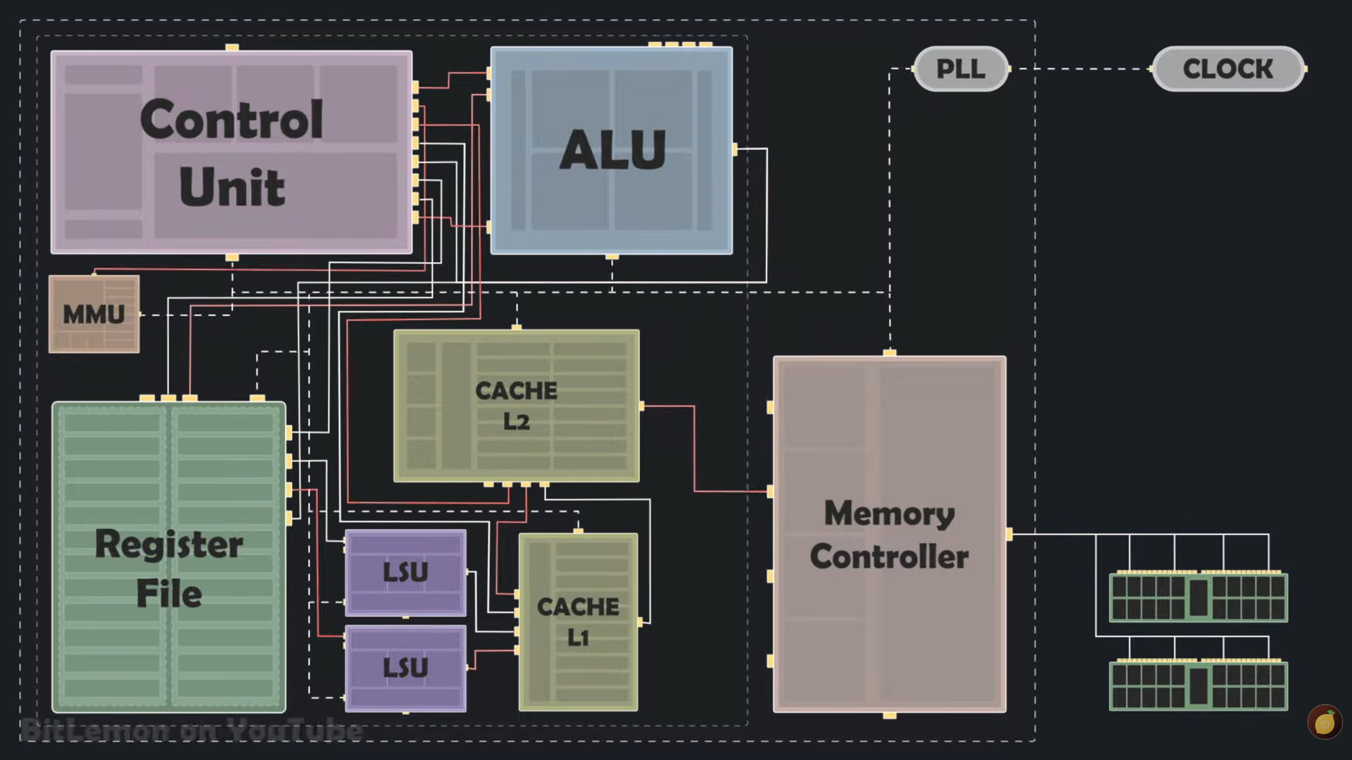
A cpu consist of:
- ALU (Arithmetic Logic Unit)
- Registers
- Control Unit (CU)
- Cache
- Clock
ALU (Arithmetic Logic Unit)
ALU (Arithmetic Logic Unit) is a part of the CPU that performs arithmetic operations and logical operations on data. it uses logic gates and stuff to calculate and compare.
It takes input from registers, processes the data, and stores the result in a destination register or memory.
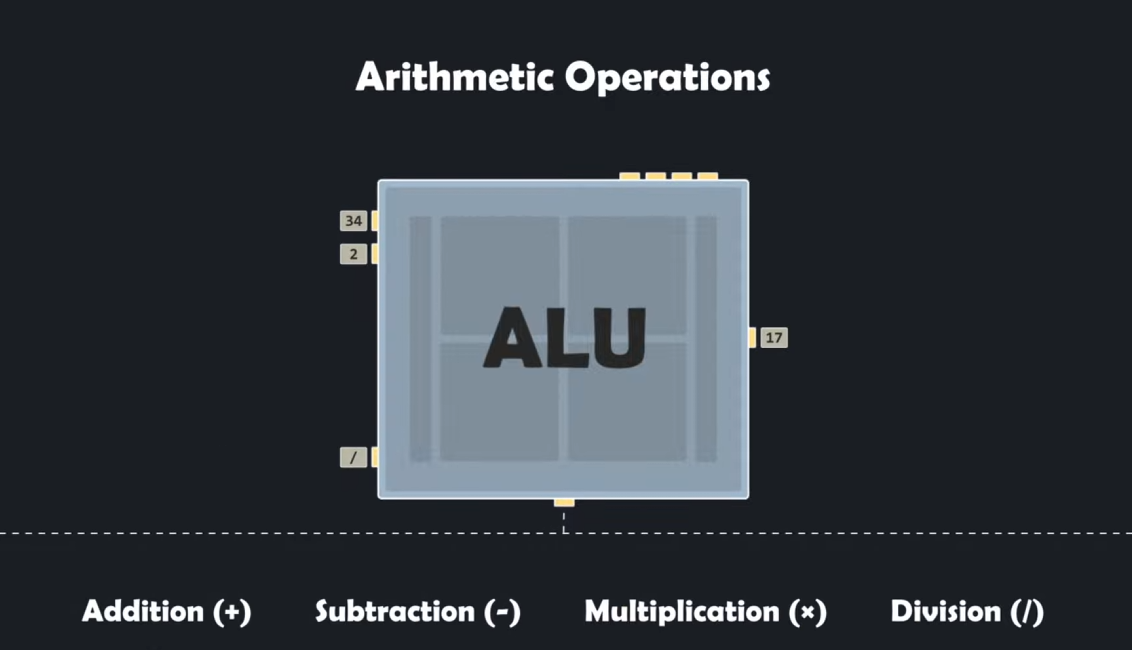
it can perform :
-
arithmetic operations like addition,subrtraction,multiplication and division.
-
logical operation like AND , OR , NOT , XOR.
-
comparison operation like Equal (==), Greater than (>), Less than(<) ,greater than equal (>=) and less than equal (<=).
-
shift operation working with binaries like shift left (<<) , shift right (>>).
-
Status Flag Generation like Common flags: Zero (Z), Carry (C), Sign (S), Overflow (V).
how alu multiply? most of cpu's alu just run the addition x times cause multiplication is addition many times . thats how many microvave dorebell adn electronic uses multiplication and advanced cpu like phone,computer have arthermetic multiplication
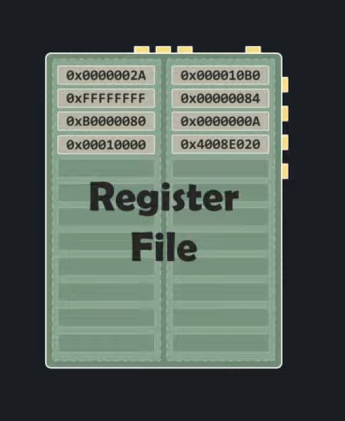
Registers
Registers are small, fast storage elements inside the CPU used to temporarily hold data, addresses, or instructions. They are directly connected to the data path and ALU, enabling high-speed access
Special-Purpose Registers (The Internal Hardware Control)
These registers have dedicated, unchangeable jobs hardwired into the CPU architecture. Programmers cannot directly use them to store arbitrary data
- Program Counter (PC) – stores the address of the next instruction.
- Instruction Register (IR) – stores the current instruction.
- Status/Flag Register – As mentioned when looking at the ALU, this register holds individual 1-bit flags (Zero, Carry, Overflow, Negative).
- Memory Address Register (MAR) – Holds the physical RAM address that the CPU wants to read from or write to
- Memory Data Register (MDR) – stores data being transferred to or from memory.
### General-Purpose Registers (GPRs)
General-Purpose Registers (GPRs) are registers inside the CPU used to store data, memory addresses, and intermediate results during program execution. These are the registers that assembly language programmers and compilers interact with directly.
Cache
Cache is a small, extremely fast memory located inside or very close to the CPU. It stores frequently used data and instructions so the CPU can access them faster than RAM.
Memory hierarchy:
Registers
↓
L1 Cache
↓
L2 Cache
↓
L3 Cache
↓
RAM
↓
SSD
Control Unit (CU)
The Control Unit (CU) is the part of the CPU that controls and coordinates all other parts of the CPU.
The Control Unit fetches instructions, decodes them, and tells the CPU components what to do.
CLOCK
A CPU clock (or clock speed) is an internal timing signal that dictates how many operations a processor can execute per second.
Measured in gigahertz (GHz), it acts like the heartbeat of your computer—A higher clock speed means the CPU can perform more clock cycles per second.
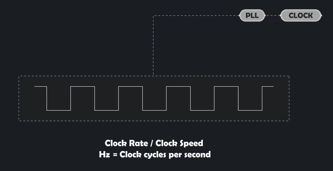 On each tick, parts of the CPU can perform work.
Fetch–Decode–Execute Cycle
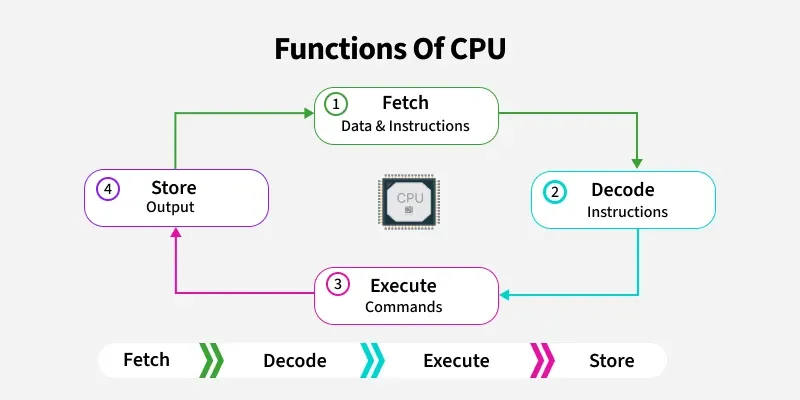 The Fetch–Decode–Execute Cycle is the continuous process by which a CPU runs a program. The CPU repeatedly fetches an instruction from memory, decodes it to determine what operation is required, and then executes it.
#### Fetch The CPU retrieves the next instruction from memory.
- The Program Counter (PC) contains the address of the next instruction.
- The address is sent to memory.
- The instruction is fetched and stored in the Instruction Register (IR).
- The PC is updated to point to the next instruction.
Decode
The Control Unit (CU) interprets the fetched instruction.
It determines: - Which operation to perform - Which registers are involved - Whether memory access is required
Execute
The CPU performs the operation.
Examples: - ALU performs arithmetic or logical operations. - LSU loads or stores data. - Registers are updated with results.
LETS RUN IT (CYCLE)
Lets run its:
MOV R1, 5
MOV R2, 3
ADD R1, R2
Our ram:
Address  Instruction
100      MOV R1, 5
104      MOV R2, 3
108      ADD R1, R2
our Program Counter (PC):
PC = 100
Step 1: Fetch
The CPU : "What instruction should I execute next?"
- The Program Counter contains: PC = 100
- The Control Unit sends address 100 to memory.
- Memory returns:
MOV R1, 5 - The instruction is placed in the Instruction Register (IR)
- The PC is updated to 104
Step 2: Decode
- The Control Unit examines:
IR = MOV R1, 5 - and breaks it into pieces:
Opcode = MOV
Destination = R1
Value = 5
- The Control Unit now understands:
Put 5 into R1
Step 3: Execute
- The Control Unit sends signals:
Write 5 into R1 - Result:
R1 = 5 - Next Cycle:
PC = 104MOV R2, 3After execution:R2 = 34.Third Cycle: Fetch:ADD R1, R2Execute:
The Control Unit tells the ALU:
Input A = R1
Input B = R2
Operation = ADD
Calculates:
5 + 3 = 8
Stores result:
R1 = 8
What Does the Clock Do?
Nothing would happen without the clock.
Tick 1 → Fetch
Tick 2 → Decode
Tick 3 → Execute
Every operation occurs in sync with clock cycles.
Cycle 1
Fetch MOV R1, 5
Decode
Execute

Cycle 2
Fetch MOV R2, 3
Decode
Execute

Cycle 3
Fetch ADD R1, R2
Decode
Execute
Note: This is a simplified model. Real CPUs may use multiple clock cycles for each stage and can execute multiple stages simultaneously using pipelining.
memory
when we start a program the code stored in binary in SSD/HDD get transtered to ram (random aceess memory)
a program cannt directly access the physical memory.
Virtual memory is a fake memory space that the operating system gives to each program.
Virtual Address    Physical RAM Address
1000               500000
1001               500001
1002               500002
the work of converting virtual memory to physical memory is work of MMU in CPU.
A Memory Management Unit (MMU) is a computer hardware component that acts as a bridge between the CPU and main memory (RAM). Its primary job is to translate virtual memory addresses generated by running programs into physical addresses in RAM.
The MMU looks in a table created by the OS called a page table.
Program
   ↓
Virtual Address 1000
   ↓
Translation
   ↓
Physical RAM 500000
VIRTUAL memory
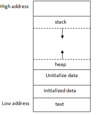
TEXT (CODE)
The text segment is the area of a running program's memory that contains the program's executable instructions.
mov [rbp-4], 5
mov eax, 0
ret
your program starts, the operating system loads these instructions into memory, and the CPU reads them one by one from the text segment to know what actions to perform.
DATA
1. Initialized data
Initialized data is memory reserved for variables that already have a value before the program starts running.
int score = 100;   // Initialized data
int lives = 3;     // Initialized data
2. Uninitialized data
Uninitialized data is memory reserved for variables that exist but were not given an initial value in the program.
int score;         // Uninitialized data
int lives;         // Uninitialized data
The operating system typically sets uninitialized global/static variables to zero when the program starts.
The important thing is that these examples are global variables (declared outside functions). If they're declared inside a function, they usually go on the stack, not in these segments.
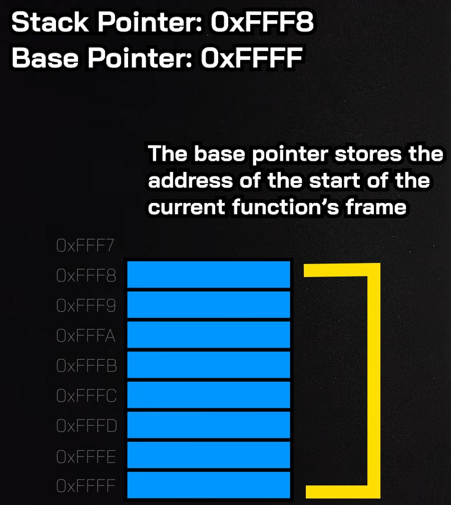
STACK
The stack is a region of RAM that a program uses to manage function calls and local variables.
 the image is reversed for understanding
But stack is FIFO (First In First Out ) from bottom.
Stock fame is created for a function.
Base pointer :- the start of the function frame or stack.
Stock Pointer :- Top of stock frame.
LETS RUN THIS CODE
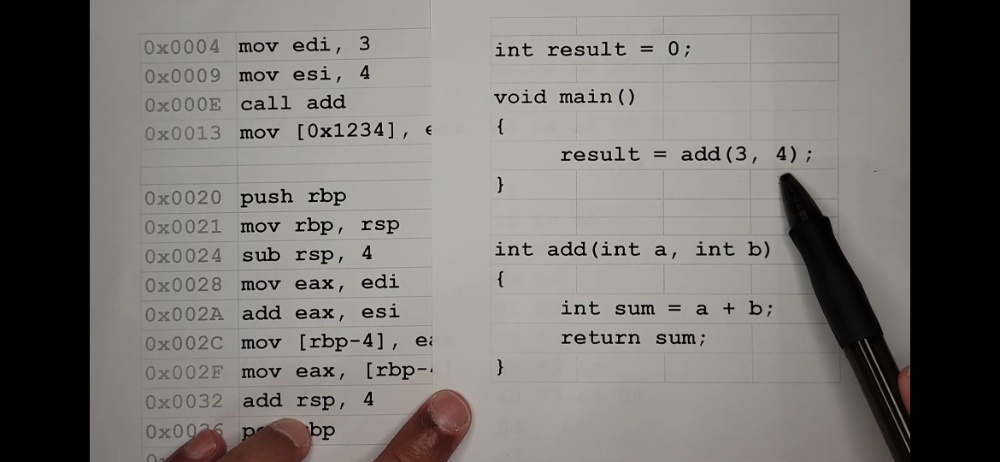
C CODE:
int result = 0;

void main()
{
    result = add(3, 4);
}

int add(int a, int b)
{
    int sum = a + b;
    return sum;
}
ASSEMBLY:
; --- Inside main() ---
0x0004  mov edi, 3
0x0009  mov esi, 4
0x000E  call add
0x0013  mov [0x1234], eax    ;

; --- Inside add() ---
0x0020  push rbp
0x0021  mov rbp, rsp
0x0024  sub rsp, 4
0x0028  mov eax, edi
0x002A  add eax, esi
0x002C  mov [rbp-4], eax
0x002F  mov eax, [rbp-4]
0x0032  add rsp, 4
0x0036  pop rbp
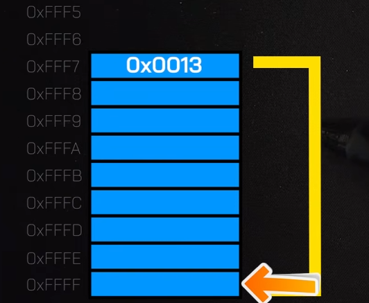
OUR STACK RIGHT NOW:
- first this code runs
0x0004  mov edi, 3
0x0009  mov esi, 4
this are the args cpu stores in register for later
- then we call add function
0x000E call add
The CPU pushes the RETURN ADDRESS next address (0x0013) onto the Stack .so it knows where to return later.
Then, it violently jumps the Instruction Pointer down to address 0x0020. main() is now paused.

Now we have to make stack space for int sum = a + b; we need 4 bytes( int size in C) to store result of sum variable. to make 4 bytes fo stack or frame for add() function.
-
0x0020: push rbpIt takes main's Base Pointer which is currently Main() function base0xFFFFand saves it on the stack.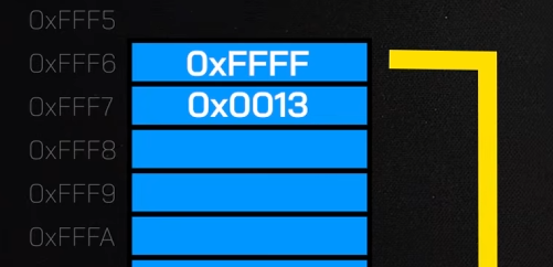
-
0x0021: mov rbp, rsp
It moves the Base Pointer (rbp) to meet the Stack Pointer (rsp) which is 0xFFF5. The base of our new sandbox is locked in.
Both Base Pointer (rbp) and Stack Pointer (rsp) are on top of the stack we can now make new space for add().
3 .0x0024: sub rsp, 4
It subtracts 4 bytes (Int Size) from the Stack Pointer.
This stretches the stack downward, creating a 4-byte empty pocket. This pocket is reserved for your local variable, int sum.
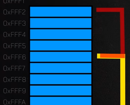
subtracting because stack goes top to bottom
This pocket is reserved for your local variable, int sum.
0x0028: mov eax, ediIt copies the 3 (from edi) into the math register eax.0x002A: add eax, esiIt adds the 4 (from esi) to the 3 inside eax. Now, eax equals 7.
eax = 7
0x002C: mov [rbp-4], eaxnow we take 7 from eax. And put it in the space we made of 4 bytes.
sum officially now equals 7.
## return sum; (ENDING)
6 .0x002F: mov eax, [rbp-4]
It copies the value of sum (7) back into the eax register.
In computing, the eax register is the designated "delivery truck" used to carry a function's return value back to the caller.
0x0032: add rsp, 4while subtract create new allocation stack, addition delete stack.
It adds 4 bytes back to the Stack Pointer. The pointer moves up, instantly erasing/deallocating the local variable sum.
0x0036: pop rbpIt restores main's old Base Pointer back into the rbp register. Now Base Pointer is again0xFFFF
pop also means remove the slat sitting on top
ret
Now it top there is return address sitting [0x0013]
so it jump back to the given address hence return
0x0013 mov [0x1234], eax
REGISTERS
COST TIME
Register access - 1ns
L1 Cache - 2ns
L2 Cache - 7ns
L3 Cache - 15ns
Main Memory - 100 ns
SSD - 150 us
HDD -10 ms
| 64-bit | 32-bit | 16-bit | 8-bit | Purpose |
|---|---|---|---|---|
| RAX | EAX | AX | AL | Return values, arithmetic |
| RBX | EBX | BX | BL | General storage |
| RCX | ECX | CX | CL | Counter, loops |
| RDX | EDX | DX | DL | Multiplication, division |
| RSI | ESI | SI | SIL | Source pointer |
| RDI | EDI | DI | DIL | Destination pointer |
| RBP | EBP | BP | BPL | Base Pointer |
| RSP | ESP | SP | SPL | Stack Pointer |
| R8 | R8D | R8W | R8B | General purpose |
| R9 | R9D | R9W | R9B | General purpose |
| R10 | R10D | R10W | R10B | General purpose |
| R11 | R11D | R11W | R11B | General purpose |
| R12 | R12D | R12W | R12B | General purpose |
| R13 | R13D | R13W | R13B | General purpose |
| R14 | R14D | R14W | R14B | General purpose |
| R15 | R15D | R15W | R15B | General purpose |
Special Registers
RIP | Instruction Pointer RFLAGS | CPU Flags Register
RAX = Return value RBX = General storage RCX = 1st argument (Windows x64) RDX = 2nd argument (Windows x64) R8 = 3rd argument (Windows x64) R9 = 4th argument (Windows x64)
RSP = Stack Pointer RBP = Base Pointer RIP = Current instruction
RFLAGS Bits
ZF = Zero Flag CF = Carry Flag OF = Overflow Flag SF = Sign Flag PF = Parity Flag AF = Auxiliary Carry DF = Direction Flag IF = Interrupt Flag